Lighting Models In Unity
- santosh nalla
- May 16, 2023
- 11 min read
In computer graphics, lighting models are used to simulate the behavior of light interacting with surfaces in a 3D scene. These models utilize algorithms to determine the illumination of each pixel on the screen.
In shader programming, the calculation of lighting can be performed either per-vertex or per-fragment. While computing the color for each vertex and interpolating it is faster than computing it for each fragment, per-fragment calculations produce more realistic results.
In this blog, we will be exploring lighting calculations in the fragment shader, which can be slower but more accurate than per-vertex calculations.
Topics we will be discussing here
Ambient
Diffuse (Lambert Light Model)
Specular
Phong Model
Blinn-Phong Model
4. Total Lighting = Ambient + Diffuse + Specular
Ambient Color
Ambient light is the light that is present in a scene without a specific light source. It is the general illumination that is present even when no other light sources are present.
The ambient color affects how all objects in the scene are lit and can help to create a specific mood or atmosphere. For example, a scene with a blue ambient color might have a cool and calming feeling, while a scene with a red ambient color might feel intense and dramatic.
In Unity, the ambient color can be set in the Lighting window under the Environment section. By adjusting the ambient color, you can fine-tune the lighting of your scene and create the desired visual impact.
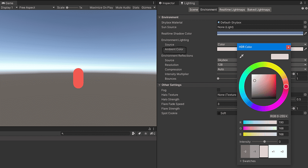
Lets try to write a simple shader code to apply this environmental lighting on to a model.
 fixed4 frag (v2f i) : SV_Target
     {
         fixed4 col = tex2D(_MainTex, i.uv) * _Color;

         //----------------------AMBIENT LIGHTING------------------
         float3 ambient_color = UNITY_LIGHTMODEL_AMBIENT *_Ambient;
         col.rgb += ambient_color;

         return col;
     }
This calculates the ambient color by multiplying the UNITY_LIGHTMODEL_AMBIENT value, which is a global value that represents the overall brightness of the ambient light in the scene, by the _Ambient color value, which is a custom property set in the material of the object being rendered. The resulting value is a float3 vector representing the RGB components of the ambient color.
The next line adds the ambient color to the color value calculated earlier, using the "+=" operator. This means that the RGB components of the ambient color are added to the corresponding components of the color value.
Full Code:
Shader "SanShaders/AmbientLight"
{
    Properties
    {
        _Color("Main Color", Color) = (1,1,1,1)
        _MainTex ("Texture", 2D) = "white" {}
        _Ambient ("Ambient Color", Range(0,1)) = 1
    }
    SubShader
    {
        Tags { "RenderType"="Opaque" }
        LOD 100

        Pass
        {
            CGPROGRAM
            #pragma vertex vert
            #pragma fragment frag

            #include "UnityCG.cginc"

            struct appdata
            {
                float4 vertex : POSITION;
                float2 uv : TEXCOORD0;
            };

            struct v2f
            {
                float2 uv : TEXCOORD0;
                float4 vertex : SV_POSITION;
            };

            sampler2D _MainTex;
            float4 _MainTex_ST;
            float _Ambient;
            float4 _Color;

            v2f vert (appdata v)
            {
                v2f o;
                o.vertex = UnityObjectToClipPos(v.vertex);
                o.uv = TRANSFORM_TEX(v.uv, _MainTex);
                return o;
            }

            fixed4 frag (v2f i) : SV_Target
            {
                fixed4 col = tex2D(_MainTex, i.uv) * _Color;

                //----------------------AMBIENT LIGHTING------------------
                float3 ambient_color = UNITY_LIGHTMODEL_AMBIENT *_Ambient;
                col.rgb += ambient_color;
                return col;
            }
            ENDCG
        }
    }
}
Diffuse Reflection
Diffuse reflection is a fundamental concept in the field of optics and computer graphics. It refers to the scattering of light by a surface in various directions, rather than reflecting it in a specific direction like a mirror. When light strikes a surface, it interacts with the microscopic irregularities on the surface, causing it to scatter in different directions.
Diffuse reflection occurs because surfaces are not perfectly smooth at the microscopic level. Instead, they have tiny bumps, grooves, or other irregularities that cause light to bounce off in different directions. This scattered light creates a diffused, softer appearance on the surface.
The behavior of diffuse reflection can be described using Lambert's cosine law, which states that the intensity of the reflected light is proportional to the cosine of the angle between the incident light direction and the surface normal. This means that the intensity of the reflected light is stronger when the incident light is perpendicular to the surface and weaker when the incident light is at a more oblique angle.
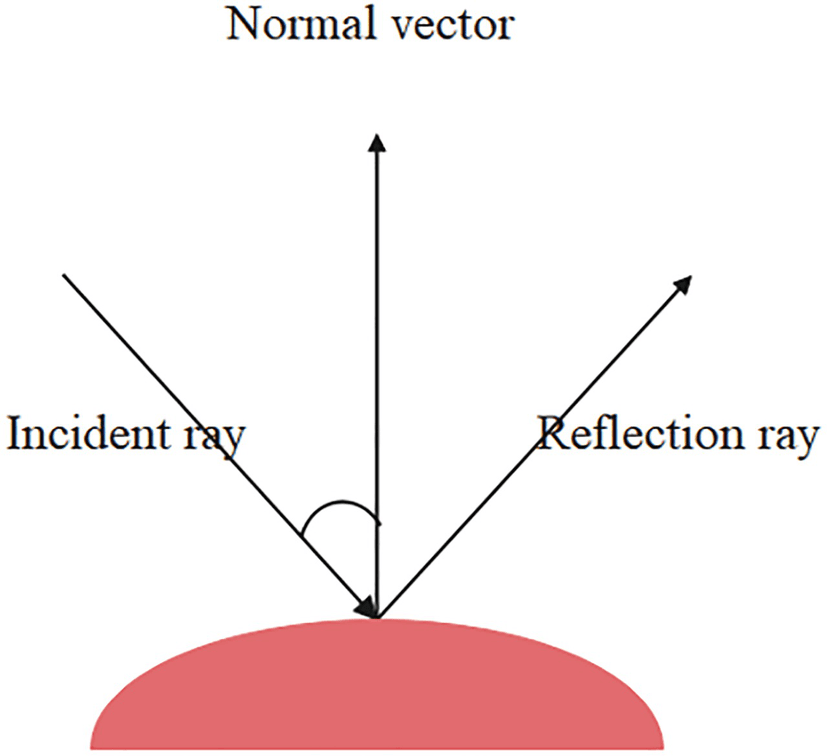
View Independence: In the Lambert lighting model, the surface's apparent brightness does not change based on the viewpoint or the position of the observer. This means that no matter from which angle you look at the surface, the perceived brightness remains constant.
Incident Light Ray: The incident light ray represents the direction from the light source to the surface point being illuminated. It indicates the path that light takes when it reaches the surface. The angle between the incident light ray and the surface normal plays a crucial role in determining the brightness factor of the pixel.
Surface Normal: The surface normal is a vector that is perpendicular to the surface at a given point. It defines the orientation or facing direction of the surface. The surface normal helps in understanding how the surface is positioned with respect to the incident light ray.
Angle between Incident Light Ray and Surface Normal: The cosine of the angle between the incident light ray and the surface normal is used to calculate the brightness factor for the pixel. The Lambert lighting model utilizes the dot product of these two vectors to determine this angle.
When the incident light ray is perpendicular (at a 90-degree angle) to the surface normal, the dot product is maximum, resulting in the highest brightness factor.
As the angle between the incident light ray and the surface normal increases (becoming more oblique), the dot product decreases, leading to a decrease in the brightness factor.
When the incident light ray is parallel (at a 0-degree angle) to the surface normal, the dot product is zero, resulting in no contribution to the brightness.
Brightness Factor: The brightness factor, derived from the dot product of the incident light ray and the surface normal, determines the amount of diffuse reflection or scattering of light from the surface. It is proportional to the cosine of the angle between the two vectors. A larger angle results in a smaller brightness factor, leading to a darker appearance, while a smaller angle produces a larger brightness factor, resulting in a brighter appearance.
By considering the angle between the incident light ray and the surface normal, the Lambert lighting model accurately simulates how light scatters and reflects off a surface. It ensures that the perceived brightness remains consistent, regardless of the viewing direction, creating a visually pleasing and view-independent lighting effect.
Formula:
diffuse = max(0, dot(surfaceNormal, lightDirection)) * lightColor * materialColor * lightIntensity;Code:
Vertex Shader:
v2f vert (appdata v)
    {
        v2f o;
        o.vertex = UnityObjectToClipPos(v.vertex);
        o.uv = TRANSFORM_TEX(v.uv, _MainTex);
        o.normal = UnityObjectToWorldNormal(v.normal);
        return o;
    }
NOTE:
o.normal = UnityObjectToWorldNormal(v.normal);It is worth noting here that, we are converting normal vector of a vertex from object space to world space.
v.normal: This refers to the normal vector component of the input structure v. It represents the normal vector of the vertex in object space, which is the local coordinate system of the object being rendered.
UnityObjectToWorldNormal(): This is a Unity function that transforms the normal vector from object space to world space. It takes the object-space normal v.normal as input and returns the world-space normal.
o.normal: This refers to the normal vector component of the output structure o. It represents the normal vector of the vertex in world space, which describes the orientation or facing direction of the surface at that vertex.
Fragment Shader:
fixed4 frag (v2f i) : SV_Target
   {
      //N: Normal Vector - Note this is in the world space
      float3 N = i.normal;

       //L: Direction Light direction vector
       //_WorldSpaceLightPos0 can be anything. Either direction light direction or point light position. But in base pass(first pass), it is always directional light direction!!
      float3 L = _WorldSpaceLightPos0.xyz;


                //----------------------DIFFUSE LIGHTING : LAMBERT LIGHT MODEL-------------------------
       float3 diffuseLight = max(0,dot(N,L)) * _LightColor0.xyz * _LightIntensity;

        return float4(diffuseLight, 1);
    }
i.normal: The input structure i contains the interpolated world-space normal vector normal, representing the surface orientation at the current fragment.
N = i.normal: The world-space normal vector is assigned to the variable N for further calculations.
_WorldSpaceLightPos0.xyz: This represents the direction of the light source or the position of a point light in world space. It is stored in the shader variable _WorldSpaceLightPos0.
dot(N, L): The dot product of the world-space normal vector N and the light direction vector L is calculated. This dot product gives the cosine of the angle between the normal vector and the light direction, which determines the amount of light falling on the surface.
max(0, dot(N, L)): The result of the dot product is clamped between 0 and the maximum value. This ensures that only positive values contribute to the final diffuse lighting, while negative values are clamped to 0.
_LightColor0.xyz: This represents the color of the light source, stored in the shader variable _LightColor0.
_LightIntensity: This is the intensity or brightness of the light source, stored in the shader variable _LightIntensity.
max(0, dot(N, L)) * _LightColor0.xyz * _LightIntensity: The clamped dot product is multiplied by the light color and intensity to calculate the diffuse lighting.
float4(diffuseLight, 1): The diffuse lighting color is returned as a float4 value, where diffuseLight represents the RGB values of the diffuse lighting, and 1 represents the alpha channel.
In the above code, i didn't take material color into consideration, but you can multiply that along with these.
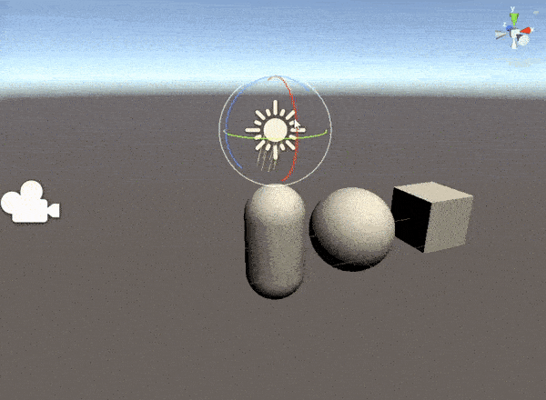
Specular Reflection
Specular reflections refer to the phenomenon of light bouncing off a surface in a mirror-like manner. Specular reflections are responsible for creating shiny and glossy highlights on objects. They enhance the perception of materials with reflective properties, such as metal or polished surfaces.
Specular reflections in Unity shaders are typically computed using the Blinn-Phong or Phong lighting models. These models calculate the reflection of light based on the viewing direction, the surface normal, and the direction of the light source.
The specular reflection calculation involves the following components:
Viewing Direction: The direction from which the viewer or camera is observing the scene. It helps determine the angle at which the surface reflects light back to the viewer.
Surface Normal: The normalized vector perpendicular to the surface at each point. It defines the orientation of the surface and plays a crucial role in determining the direction of the specular reflection.
Light Direction: The direction from the surface point towards the light source. It indicates the path that light takes when it reaches the surface and affects the intensity and direction of the specular reflection.
Specular Power or Shininess: A parameter that controls the tightness or concentration of the specular highlight. Higher specular power values result in smaller and more focused specular highlights, while lower values produce larger and more spread-out highlights.
Specular - Phong
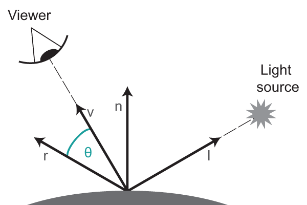
The Phong lighting model calculates the specular reflection by following these steps:
Compute the reflected light direction by reflecting the incident light vector across the surface normal. (R)
Calculate the dot product of the reflected light direction(R) and the view direction(V)(direction from the fragment towards the viewer).
Raise the dot product to the power of the specular exponent (shininess) to control the tightness or concentration of the specular highlight.
Multiply the result by the light color, material color, and specular intensity to determine the final specular reflection.
Vertex Shader:
v2f vert (appdata v)
    {
        v2f o;
        //This is in clip position remember!!
         o.vertex = UnityObjectToClipPos(v.vertex);
         o.uv = TRANSFORM_TEX(v.uv, _MainTex);
         o.normal = UnityObjectToWorldNormal(v.normal);

        //vertex position in world space!!
         o.worldFragmentPosition = mul(unity_ObjectToWorld, v.vertex);

         return o;
     }
In the above vertex shader it is worth noting, we are calculating the world Position for each fragment by multiplying with unity_ObjectToWorld (This is a matrix that transforms vertices from object space to world space. It represents the transformation applied to the object or mesh in the scene to position it correctly in the world.)
Fragment Shader:
fixed4 frag (v2f i) : SV_Target
    {
          //N: Normal Vector : world space!!
          float3 N = normalize(i.normal);

          //L: Direction Light direction vector
          //_WorldSpaceLightPos0 can be anything. Either direction light direction or point light position. But in base pass(first pass), it is always directional light direction!!
          float3 L = normalize(_WorldSpaceLightPos0.xyz);

          //V: View Vector
          float3 V = normalize(_WorldSpaceCameraPos - i.worldFragmentPosition);

          //-------SPECULAR LIGHTING : PHONG LIGHTING MODEL-------
          //R - Reflected Vector
          //-L cz the light vector is always from the surface. But for refection we need a vector into the surface
         float3 R = normalize(reflect(-L, N));

         float3 specularLight_Phong = max(0, dot(V, R));
         specularLight_Phong = pow(specularLight_Phong, _Gloss);
         return float4(specularLight_Phong, 1);
   }
i.normal: The input structure i contains the interpolated world-space normal vector normal, representing the surface normal at the current fragment.
N = normalize(i.normal): The world-space normal vector is normalized and assigned to the variable N for further calculations. Normalizing the vector ensures consistent lighting calculations.
_WorldSpaceLightPos0.xyz: This represents the direction of the light source or the position of a point light in world space. It is stored in the shader variable _WorldSpaceLightPos0.
L = normalize(_WorldSpaceLightPos0.xyz): The light direction vector is normalized and assigned to the variable L. Normalization ensures the direction vector has a unit length for accurate calculations.
_WorldSpaceCameraPos: This represents the position of the camera in world space. It is stored in the shader variable _WorldSpaceCameraPos.
V = normalize(_WorldSpaceCameraPos - i.worldFragmentPosition): The view vector is computed by subtracting the world space position of the fragment from the camera position and normalizing it. It represents the direction from the fragment towards the camera or viewer.
reflect(-L, N): The reflect function calculates the reflected vector R by reflecting the negated light direction vector -L about the surface normal N. This simulates the direction of the specular reflection based on the incident light and the surface normal.
specularLight_Phong = max(0, dot(V, R)): The dot product between the view vector V and the reflected vector R is calculated. This represents the cosine of the angle between the view vector and the reflected vector and determines the strength of the specular reflection.
pow(specularLight_Phong, _Gloss): The specular reflection is raised to the power of the glossiness factor _Gloss. This factor controls the concentration and tightness of the specular highlight.
return float4(specularLight_Phong, 1): The resulting specular lighting color is returned as a float4 value, where specularLight_Phong represents the intensity of the specular reflection, and 1 represents the alpha channel.
Specular -Blinn-Phong
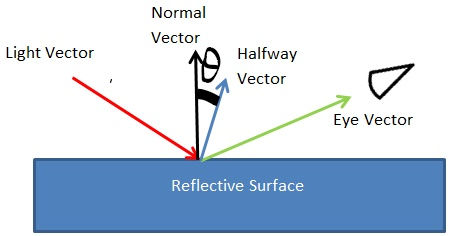
One limitation of the Phong lighting model is that it involves expensive calculations of the reflected light direction in the fragment shader, which can impact performance.
The Blinn-Phong lighting model, introduced by James F. Blinn, addresses the performance issue of the Phong model by using a modified approach. It replaces the calculation of the reflected light direction with a half-vector calculation.
The key steps of the Blinn-Phong lighting model are as follows:
Compute the halfway vector between the light direction and the view direction. This is the normalized sum of these two vectors.
Calculate the dot product of the halfway vector and the surface normal.
Raise the dot product to the power of the specular exponent (shininess) to control the tightness or concentration of the specular highlight.
Multiply the result by the light color, material color, and specular intensity to determine the final specular reflection.
 fixed4 frag (v2f i) : SV_Target
     {
         //N: Normal Vector
         float3 N = normalize(i.normal);

         //L: Direction Light direction vector
         //_WorldSpaceLightPos0 can be anything. Either direction light direction or point light position. But in base pass(first pass), it is always directional light direction!!
         float3 L = normalize(_WorldSpaceLightPos0.xyz);

         //V: View Vector
         float3 V = normalize(_WorldSpaceCameraPos - i.worldFragmentPosition);

         //---------SPECULAR LIGHTING : BLINN_PHONG LIGHTING MODEL-------
         //Half Vector
         float3 H = normalize(L + V);

         float3 specularLight_BlinnPhong = max(0, dot(H, N));
         float specularExponent = exp2((_Gloss * 11) + 2);
         specularLight_BlinnPhong = pow(specularLight_BlinnPhong, specularExponent);
         specularLight_BlinnPhong = specularLight_BlinnPhong * _LightColor0.xyz;

          return float4(specularLight_BlinnPhong, 1);
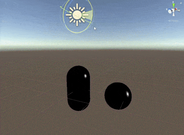
            }
Now for the final lighting model:
Phong Reflection = Ambient + Diffuse + Specular (Phong)
Blinn-Phong Reflection = Ambient + Diffuse + Specular(Blinn-Phong)
Full Code:
Shader "Unlit/Compositing_Diff+Specular"
{
    Properties
    {
        _MainTex ("Texture", 2D) = "white" {}
        _Color("Color", Color) = (1,1,1,1)
        _Gloss("Gloss", Range(0,1)) = 1
    }
    SubShader
    {
        Tags { "RenderType"="Opaque" }
        LOD 100

        Pass
        {
            CGPROGRAM
            #pragma vertex vert
            #pragma fragment frag

            #include "UnityCG.cginc"
            #include "Lighting.cginc"
            #include "AutoLight.cginc"

            struct appdata
            {
                float4 vertex : POSITION;
                float2 uv : TEXCOORD0;
                float3 normal : NORMAL;
            };

            struct v2f
            {
                float2 uv : TEXCOORD0;
                float4 vertex : SV_POSITION;
                float3 normal : TEXCOORD1;
                float3 worldFragmentPosition : TEXCOORD2;
            };

            sampler2D _MainTex;
            float4 _MainTex_ST;
            float _Gloss;
            float4 _Color;

            v2f vert (appdata v)
            {
                v2f o;
                //This is in clip position remember!!
                o.vertex = UnityObjectToClipPos(v.vertex);
                o.uv = TRANSFORM_TEX(v.uv, _MainTex);
                o.normal = UnityObjectToWorldNormal(v.normal);

                //vertex position in world space!!
                o.worldFragmentPosition = mul(unity_ObjectToWorld, v.vertex);

                return o;
            }

            fixed4 frag (v2f i) : SV_Target
            {
                //N: Normal Vector
                float3 N = normalize(i.normal);

                //L: Direction Light direction vector
                //_WorldSpaceLightPos0 can be anything. Either direction light direction or point light position. But in base pass(first pass), it is always directional light direction!!
                float3 L = normalize(_WorldSpaceLightPos0.xyz);

                //V: View Vector
                float3 V = normalize(_WorldSpaceCameraPos - i.worldFragmentPosition);

                //----------------------DIFFUSE LIGHTING : LAMBERT LIGHTING MODEL-----------------------
                float3 lambert = max(0, dot(N, L));
                float diffuseLight = lambert * _LightColor0.xyz;

                //.
                //.
                //.
                //.
                //.
                //.

                //----------------------SPECULAR LIGHTING : BLINN_PHONG LIGHTING MODEL-----------------------
                //Half Vector
                float3 H = normalize(L + V);

                float3 specularLight_BlinnPhong = max(0, dot(H, N));
                specularLight_BlinnPhong = specularLight_BlinnPhong * (lambert > 0); //counter some wield effect. But yes for leaning purpose ignore this :P

                float specularExponent = exp2((_Gloss * 11) + 2); //Specular exponent
                specularLight_BlinnPhong = pow(specularLight_BlinnPhong, specularExponent);
                specularLight_BlinnPhong = specularLight_BlinnPhong * _LightColor0.xyz;

                //.
                //.
                //.
                //.
                //.
                //.

                //----------------------COMPOSITING : DIFFUSE(LAMBERT) + SPECULAR(BLINN_PHONG)-----------------------
                return float4((diffuseLight * _Color) + specularLight_BlinnPhong, 1);
            }
            ENDCG
        }
    }
}
Haven't added ambient, but you can add if you wish.
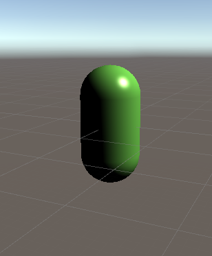
Result:


Comments